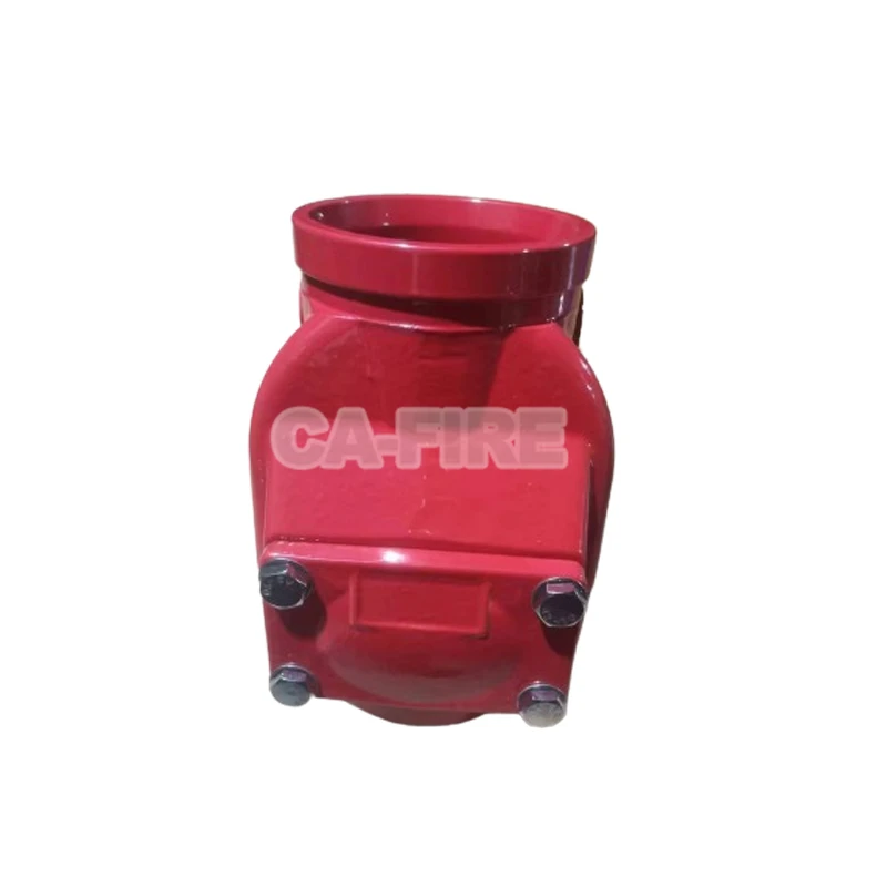


The grooved swing check valve functions as a self-acting flow control device engineered to maintain unidirectional movement of fluid within enclosed conduit networks. Its internal architecture centers on a pivoting closure element commonly designated as the clapper, which articulates around a fixed horizontal axis positioned near the upper extremity of the flow passage. This rotating component works in conjunction with a precision-machined seating surface and, in advanced configurations, incorporates a helical spring element that provides auxiliary force modulation throughout the operating cycle.
Under normal forward flow conditions, the kinetic energy and pressure head of the transported fluid act upon the downstream face of the clapper, generating sufficient torque to overcome both the gravitational moment and any spring preload that may be present. This hydraulic force causes the closure element to swing outward from its resting position, establishing an angular relationship with the flow stream that presents minimal obstruction to the passing medium. The resulting fully open configuration creates a streamlined flow trajectory with exceptionally low head loss characteristics, preserving system energy efficiency and reducing pumping power requirements.
Upon cessation of forward flow or detection of adverse pressure gradients-conditions typically arising from pump de-energization or abrupt changes in system demand-the hydraulic actuating force diminishes rapidly. The clapper assembly then initiates rotational movement back toward its original orientation under the influence of gravitational acceleration acting on its mass distribution. In spring-assisted variants, the mechanical energy stored in the compressed helical element releases simultaneously, augmenting the gravitational torque and significantly reducing the time interval required to achieve complete seating. This expedited closure response proves critical in attenuating pressure transients associated with liquid deceleration, effectively mitigating hydraulic shock phenomena that would otherwise propagate through the piping infrastructure and threaten mechanical integrity of connected equipment.
The final sealing action occurs as the clapper face establishes intimate contact with the annular seating surface machined into the valve body. Interface materials selected for this junction typically include elastomeric compounds such as ethylene propylene diene monomer or nitrile butadiene rubber, chosen for their resilience characteristics and chemical compatibility with anticipated service fluids. These polymeric elements deform under mechanical compression to fill microscopic surface irregularities, achieving bubble-tight isolation that prevents any reverse leakage or contamination of upstream system segments.