

Fire Hydrant Systems: Design Standards and Installation Best Practices
Leave a message
Understanding Fire Hydrant System Fundamentals
Definition and Primary Function
A fire hydrant system is a network of underground water pipes connected to above-ground or underground hydrant outlets, providing firefighters with immediate access to high-volume, high-pressure water supplies. System effectiveness depends on three critical parameters: adequate water supply, sufficient pressure, and accessibility.
System Components Overview
Underground Water Mains
The backbone of the system, typically constructed from ductile iron or HDPE, sized to deliver required flow rates while maintaining adequate residual pressure.
Hydrant Assemblies
Consist of the barrel, main valve, operating nut, outlet connections, and cap assemblies. Outlet sizes typically range from 65 mm to 100 mm.
Isolation Valves
Enable sections of the system to be shut down for maintenance without disrupting the entire water supply.
Types of Fire Hydrants and Their Applications
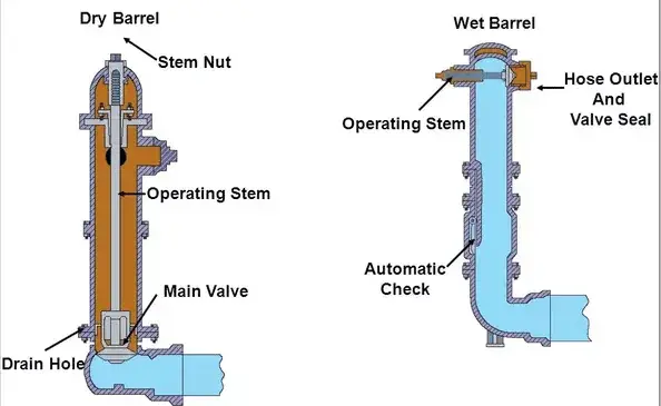
Wet Barrel Hydrants
Predominant in climates without freezing risk. Water remains in the barrel at all times, with each outlet individually controlled. Advantages: instantaneous operation, simplified maintenance, easy flow monitoring. Ideal for temperate and tropical climates.
Dry Barrel Hydrants
Essential for cold climates. The main valve is located below the frost line, with a drain port that automatically opens when closed to prevent freeze damage. Critical considerations: frost depth, drainage, and backfill material.
Pillar Hydrants
Vertical above-ground design widely used in European, Asian, and Middle Eastern markets. Robust construction for high-pressure applications, manufactured to EN 14339 and BS 750 standards.
Underground Hydrants
Concealed installation with only the surface box visible. Benefits: reduced obstruction, vandalism resistance, aesthetic integration. Require regular inspection of surface boxes.
International Design Standards
NFPA Standards
NFPA 24: Private fire service mains design, pipe materials, hydrant spacing, valve installation, and testing requirements.
NFPA 291: Fire flow testing procedures and hydrant marking systems.
European Standards
EN 14339: Requirements for underground and pillar fire hydrants, including dimensions, performance criteria, and material specifications.
EN 1074: Valves for water supply systems, covering design requirements and quality assurance.
British Standards
BS 750: Specifications for fire hydrants and surface boxes, including outlet configurations and load-bearing requirements.
Hydraulic Design and System Sizing
Water Demand Calculations
Fire flow requirements determined by empirical formulas, engineering analysis, or code-prescriptive requirements. Duration requirements: 1–2 hours for light hazard, 2–3 hours for ordinary hazard, 3–4+ hours for extra hazard.
Hydraulic Analysis
Network modeling accounts for pipe friction losses, minor losses, elevation changes, and multiple hydrant flows. Residual pressure requirements: minimum 1.0–1.5 bar at the most remote hydrant.
Pipe Sizing and Material Selection
Ductile Iron: High strength, standard for municipal systems
Steel: High-pressure capability for industrial applications
HDPE: Corrosion resistance, increasingly popular for new installations
Installation Best Practices
Site Preparation
Trench specifications: minimum 750–1,000 mm cover, proper bedding material
Soil assessment: corrosive soils may require enhanced protection
Pipe Installation
Joint types: push-on, mechanical, flanged, and restrained joints
Alignment and grade: straight alignment, minimum 1:500 slope, air release valves at high points
Hydrant Installation
Positioning: 150–300 mm from curb, outlet faces perpendicular to street
Connection to mains: tapping sleeve and valve, properly sized riser pipe, thrust blocking
Backfill and Restoration
Compacted granular bedding, hand-placed material around joints, layer-by-layer compaction, and surface restoration matching pre-construction conditions.
Testing and Commissioning
Hydrostatic Testing
Test pressure at 1.5 times working pressure for minimum 2 hours. Acceptance criteria: pressure loss within specified limits, no visible leakage.
Flow Testing
Pitot tube measurements of outlet flow velocity, residual pressure measurement at flowing and non-flowing hydrants. Document flow rates, residual pressures, and comparison to design requirements.
System Acceptance
Complete documentation including as-built drawings, test reports, material certifications, and operation and maintenance manuals.
Maintenance and Inspection
Routine Inspection
Visual inspection: physical condition, accessibility, identification markings
Operational inspection: valve operation, drain function, cap security
Annual Flow Testing
Verify flow rates, monitor residual pressures, and compare to baseline data to identify degradation trends.
Preventive Maintenance
Lubrication of operating components, touch-up of protective coatings, and scheduled gasket replacement.
Conclusion
Fire hydrant systems require careful design, quality installation, and diligent maintenance to ensure reliable performance. The selection of appropriate hydrant types, adherence to recognized standards, and comprehensive maintenance programs collectively determine system effectiveness.
CA-Fire Protection Co., Ltd. has manufactured high-quality fire hydrant systems since 2012 from our 50,000+ square meter facility. Our products meet FM Approval and UL Listing standards, with ISO 9001 quality management certification. We offer wet barrel, dry barrel, and pillar hydrants for municipal and industrial applications worldwide, with OEM and ODM capabilities available.
For more information, visit www.cafire-119.com or contact our technical team.
About CA-Fire Protection Co., Ltd. Established in 2012 in Nan'an, Quanzhou City-China's fire protection industrial center. Over 80 patents, 90+ product varieties, ISO 9001/14001/45001 certified. Committed to building CA into a leading global fire industry brand.


